Available 24/7 at
0755-82798135How to Choose the Right Inductor for DC-DC Converter Design
DC-DC converters are widely used in modern electronic systems to efficiently convert one voltage level to another. They are essential in consumer electronics, industrial equipment, automotive systems, communication devices, and embedded power designs. While semiconductors and controllers often receive the most attention, the inductor is one of the most critical components in the entire power stage.
Choosing the wrong inductor can reduce efficiency, increase heat, worsen ripple current, and even create stability problems in the converter. In contrast, selecting the right inductor helps improve performance, reduce losses, and ensure long-term reliability.
In this guide, we explain how to choose the right inductor for DC-DC converter design, what technical parameters matter most, and what mistakes should be avoided during component selection. To explore more electronic components and sourcing solutions, visit TomatoElec.
Why the Inductor Matters in DC-DC Converter Design
In a DC-DC converter, the inductor stores and releases energy during switching cycles. It helps smooth current, reduce output ripple, and support stable power conversion. The inductor directly influences converter efficiency, thermal behavior, transient response, and EMI performance.
For example, in a buck converter, the inductor carries the load current and determines ripple characteristics. In a boost converter, the inductor plays a major role in energy transfer and current stress. Because of this, inductor selection is not only about choosing an inductance value. It also requires careful review of current rating, core material, DC resistance, switching frequency, and physical size.
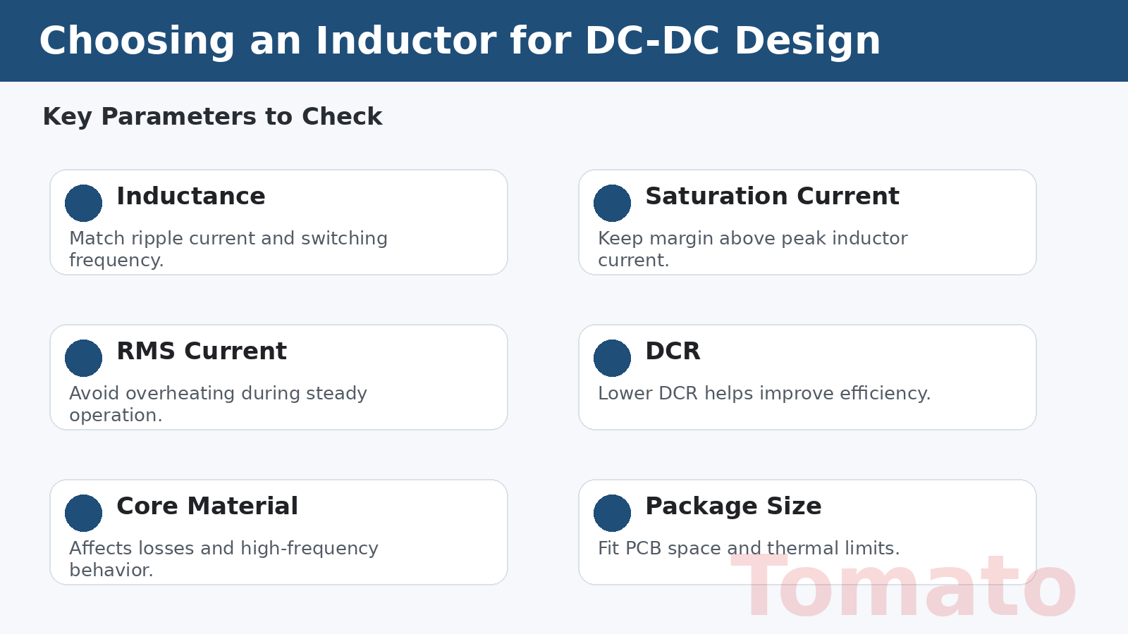
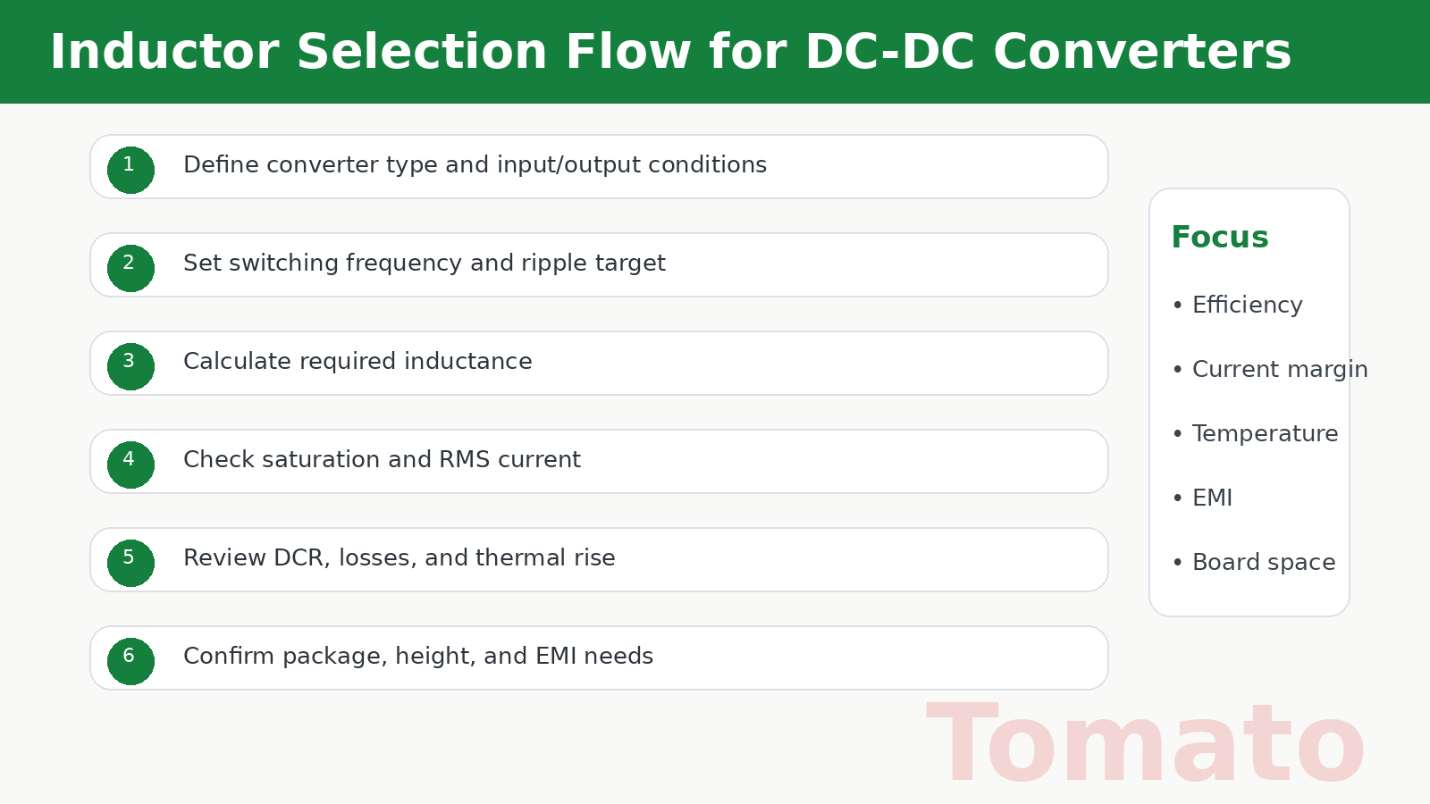
Key Parameters to Consider When Choosing an Inductor
1. Inductance Value
The inductance value, usually expressed in microhenries (µH), determines current ripple and dynamic response. A higher inductance generally reduces ripple current, while a lower inductance may improve transient response but increase ripple.
Designers usually choose the inductance based on converter topology, input voltage, output voltage, switching frequency, and target ripple current.
2. Saturation Current
Saturation current is one of the most important parameters in power inductor selection. If the inductor core saturates, inductance drops sharply and converter performance can become unstable.
The selected inductor should always provide enough margin above the expected peak inductor current.
3. RMS Current Rating
RMS current rating indicates how much current the inductor can handle continuously without overheating beyond specification. Even if saturation current is acceptable, the inductor must still be able to manage continuous operating current safely.
4. DC Resistance (DCR)
DCR directly affects conduction losses and temperature rise. A lower DCR improves efficiency and reduces self-heating, which is especially important in high-current power supplies.
5. Core Material
Core material affects frequency behavior, core losses, saturation characteristics, and EMI performance. Ferrite cores are commonly used in switching power supplies, while other materials may be selected depending on design frequency and current requirements.
6. Switching Frequency
The operating frequency of the DC-DC converter influences inductor choice. Higher switching frequencies may allow smaller inductors, but they can also increase core losses and switching losses. The inductor must be suitable for the intended frequency range.
7. Package Size and Height
Mechanical size matters in practical PCB design. The inductor must fit the board layout, meet height restrictions, and support the required thermal performance. In compact power modules and portable electronics, this becomes especially important.
8. Shielded vs Unshielded Design
Shielded inductors help reduce electromagnetic interference and are often preferred in compact or noise-sensitive systems. Unshielded inductors may offer other trade-offs in cost or structure depending on the application.
Inductor Selection for Buck and Boost Converters
Buck Converters
In buck converter design, the inductor is used to smooth the current delivered to the load. Designers typically choose inductance based on target ripple current, which is often set as a percentage of output current.
A very small inductor may result in excessive ripple and higher peak current, while an overly large inductor can slow transient response and increase component size.
Boost Converters
In boost converters, the inductor stores energy during the switch-on phase and releases it to the output during the off phase. This usually places higher stress on the inductor current, so saturation current and thermal performance are especially important.
Practical Design Balance
In both buck and boost converter design, the best choice is usually a balance between inductance, efficiency, ripple current, transient response, thermal behavior, and package constraints.
SMD vs Through-Hole Power Inductors
SMD Power Inductors
SMD inductors are commonly used in modern DC-DC converter designs because they support automated PCB assembly and compact layouts.
- Small footprint
- Good compatibility with mass production
- Suitable for compact power modules
- Easy integration into dense PCB layouts
Through-Hole Power Inductors
Through-hole inductors are still used in some prototypes, repair applications, and high-power or mechanically demanding systems.
- Strong mechanical support
- Easier manual handling in some cases
- Useful for prototyping and testing
The final choice depends on converter power level, board layout, production process, and mechanical requirements.
Common Mistakes to Avoid
Choosing by Inductance Only
Some users focus only on the inductance value and ignore current capability, DCR, or thermal performance. This can lead to poor real-world results.
Ignoring Saturation Margin
Selecting an inductor too close to peak current limits increases the risk of saturation and unstable operation.
Overlooking DCR
A high DCR may significantly reduce efficiency and increase heat, especially in high-current designs.
Using the Wrong Core Material
Core material must match switching frequency and loss requirements. Otherwise, efficiency and temperature rise may become problematic.
Ignoring Mechanical Constraints
An inductor may be electrically suitable but physically incompatible with the PCB height or layout.
Practical Tips Before Buying
Before purchasing an inductor for DC-DC converter design, confirm the following:
- Required inductance value
- Peak current and saturation margin
- RMS current requirement
- DCR target
- Switching frequency compatibility
- Core material and loss behavior
- Package size and board height
- Thermal performance and EMI considerations
- Supplier inventory and lead time
Working with a reliable electronic components supplier can reduce sourcing risk and improve design efficiency, especially for engineering development, sample builds, and production procurement.
Conclusion
Selecting the right inductor is a key part of successful DC-DC converter design. The inductor affects ripple current, efficiency, heat, EMI behavior, and long-term reliability. Instead of choosing by inductance value alone, engineers and buyers should evaluate current rating, saturation margin, DCR, core material, switching frequency, and package constraints together.
By understanding these factors, designers can improve converter performance and make more reliable sourcing decisions. Whether you are designing a compact buck converter or a high-current boost power stage, the right inductor will make a clear difference in stability and efficiency.
If you are looking for power inductors and other electronic components for your next project, visit TomatoElec to explore more inductor products or reach out through the contact page.