

Available 24/7 at
0755-82798135

Norton’s Theorem: Current Source and Parallel Resistance
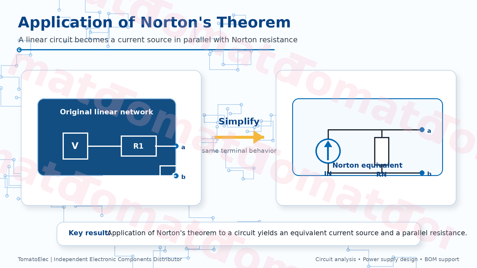
The phrase "application of Norton's theorem to a circuit yields" usually points to one direct answer: it yields a Norton equivalent circuit. That equivalent circuit contains an ideal current source in parallel with an equivalent resistance, both viewed from the same output terminals as the original network.
For students, this is often a textbook question. For engineers, it is more than a definition. Norton's theorem is useful when a complicated part of a circuit needs to be simplified before checking load current, output behavior, source resistance, or the effect of changing a connected load.
This guide explains what Norton's theorem gives you, how to calculate the Norton current and Norton resistance, how it relates to Thevenin's theorem, and where the method is still useful in power supply, sensor, load, and general circuit analysis.
What does application of Norton's theorem yield?
Application of Norton's theorem to a circuit yields a simplified equivalent circuit made of two parts: a Norton current source and a Norton resistance connected in parallel. The load is then connected across the same two terminals.
This equivalent circuit behaves the same as the original linear network from the load's point of view. The internal circuit may contain multiple voltage sources, current sources, and resistors, but at the chosen output terminals it can be replaced by a much simpler current-source model.
In short, Norton's theorem changes the question from "How do I analyze this whole circuit again?" to "What current source and parallel resistance does the load see?" That is why the theorem is useful when the load changes or when only the output behavior matters.
Norton's theorem in plain language
Norton's theorem says that any linear two-terminal network can be represented by an equivalent current source in parallel with an equivalent resistance. The two terminals are important. If you choose different terminals, you may get a different Norton equivalent.
The Norton current, usually written as IN, is the short-circuit current available at the output terminals. The Norton resistance, usually written as RN, is the resistance seen looking back into the network when independent sources are turned off, or it can be calculated from the open-circuit voltage divided by the short-circuit current.
Once the original circuit is replaced by its Norton equivalent, the load can be reconnected. Load current and load voltage can then be found more easily using current division, Ohm's law, or source transformation.
How to find the Norton equivalent
The practical steps are simple, but the details matter. Always define the output terminals first. Norton's theorem does not simplify the whole circuit in a vague way; it simplifies what the load sees at a specific pair of terminals.
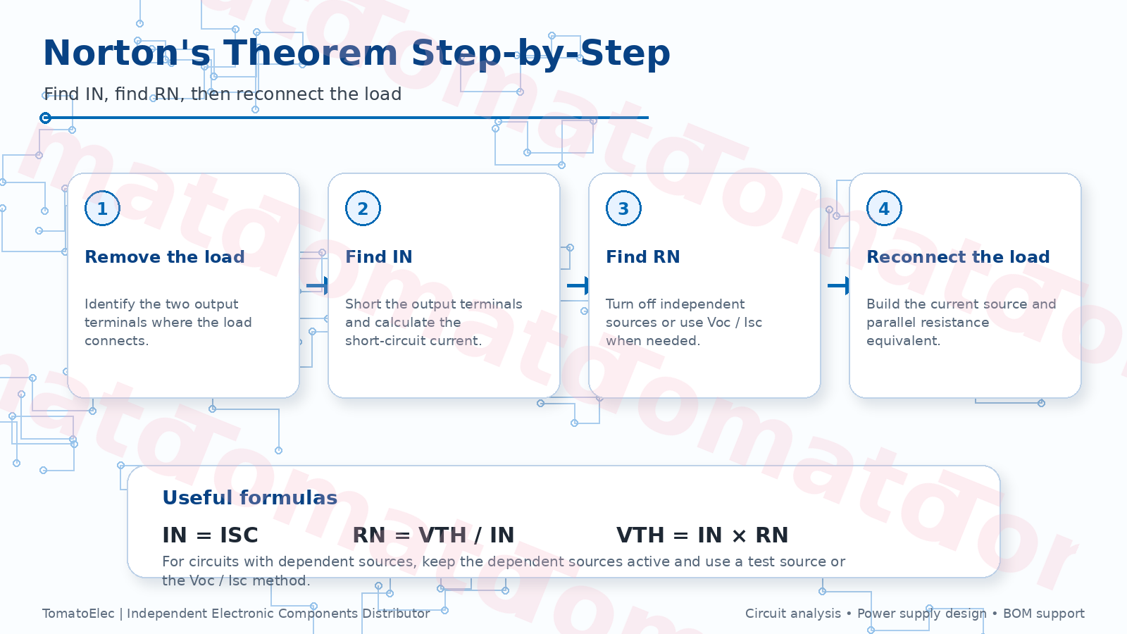
- Remove the load: Identify the two terminals where the load was connected.
- Find the Norton current: Short the output terminals and calculate the short-circuit current. This current is IN.
- Find the Norton resistance: Turn off independent voltage sources by replacing them with shorts, and turn off independent current sources by replacing them with opens. Then calculate the resistance seen from the output terminals.
- Handle dependent sources carefully: If the circuit has dependent sources, keep them active and use a test source or the open-circuit-voltage divided by short-circuit-current method.
- Build the Norton equivalent: Draw IN in parallel with RN, then reconnect the load across the same terminals.
Simple Norton theorem example
Assume a linear network is viewed from two output terminals. After analysis, its Thevenin equivalent is found to be 12 V with a 4 ohm series resistance. The Norton resistance is the same value, so:
RN = 4 ohm
The Norton current is the Thevenin voltage divided by the resistance:
IN = VTH / RN = 12 V / 4 ohm = 3 A
So the Norton equivalent is a 3 A current source in parallel with a 4 ohm resistor. If an 8 ohm load is connected across the terminals, the load current can be found by current division:
IL = IN × RN / (RN + RL) = 3 A × 4 / (4 + 8) = 1 A
This gives a load voltage of:
VL = IL × RL = 1 A × 8 ohm = 8 V
The same result would be obtained from the Thevenin equivalent. Norton and Thevenin are two forms of the same terminal behavior. Norton is often more convenient when the analysis is focused on current division or parallel load behavior.
Norton vs Thevenin equivalent circuits
Norton's theorem and Thevenin's theorem are closely related. Thevenin uses a voltage source in series with a resistance. Norton uses a current source in parallel with a resistance. The two models can be converted into each other.
| Item | Norton equivalent | Thevenin equivalent |
|---|---|---|
| Source type | Current source | Voltage source |
| Resistance position | Parallel with source | Series with source |
| Main current relation | IN = VTH / RN | VTH = IN × RN |
| Resistance relation | RN = RTH | RTH = RN |
| Useful when | Current division and parallel load behavior are easier to analyze | Voltage division and series load behavior are easier to analyze |
In real design work, engineers may switch between the two forms depending on which one makes the next calculation easier. Neither form is more "correct"; they are equivalent views of the same linear network at the selected terminals.
Practical applications in circuit design
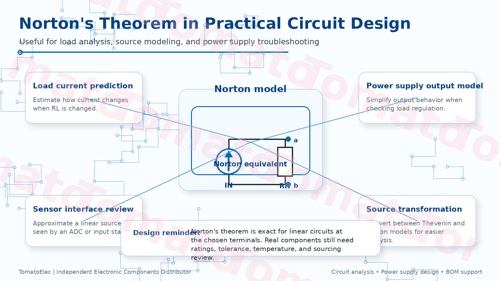
Norton's theorem is often taught in basic circuit theory, but it is still useful in practical design review. It helps simplify the part of a circuit that drives a load, so the engineer can focus on output current, load voltage, and how the circuit behaves when the load changes.
Common applications include power supply output analysis, sensor interface review, current source modeling, load regulation checks, source transformation, and troubleshooting of linearized circuits. It is especially useful when a load is connected in parallel with an equivalent resistance and the current division is easier to see in Norton form.
Power supply and load analysis example
One practical use of Norton's theorem is to estimate how a load affects a source or power supply output. A complicated source network can be reduced to a Norton current source and a parallel Norton resistance. The load can then be connected across the output, and the current division becomes clear.
This does not replace detailed power supply design. Switching converters, regulators, and protection circuits can be nonlinear and frequency dependent. But for a linearized operating point or a simplified DC model, Norton's theorem helps engineers understand how source resistance and load resistance interact.
For buyers and sourcing teams, this is also a useful reminder: circuit analysis may simplify the network, but real components still need the correct power rating, tolerance, voltage rating, package, temperature range, and reliability level.
Common mistakes when using Norton's theorem
Norton's theorem is simple, but it is easy to apply incorrectly. The most common mistakes are not mathematical; they come from choosing the wrong terminals or forgetting circuit assumptions.
- Using the wrong terminals: The Norton equivalent depends on where the load is connected.
- Confusing Norton current with load current: IN is the short-circuit current, not necessarily the current through a real load.
- Turning off dependent sources: Dependent sources should stay active during equivalent resistance calculation.
- Ignoring nonlinearity: Norton's theorem applies directly to linear circuits. Nonlinear devices may only be approximated around an operating point.
- Forgetting AC impedance: In AC analysis, resistance may need to be treated as impedance at a given frequency.
- Assuming the internal circuit is physically unchanged: The Norton model matches terminal behavior, not internal power dissipation or internal component stress.
Component and sourcing notes
A Norton equivalent is a model. It helps engineers calculate circuit behavior, but it does not remove the need to choose real components correctly. Resistors, current-sense components, power devices, connectors, capacitors, and protection parts must still be selected according to voltage, current, thermal, tolerance, package, and reliability requirements.
TomatoElec is an electronic components independent distributor supporting buyers, engineers, and procurement teams with sourcing for passive components, power management components, sensors, diodes, and other electronic parts. If your circuit design or repair project requires BOM sourcing support, availability checks, or alternative component review, you can send the full part number list for checking.
For sourcing requests, please provide the original MPN, quantity, target delivery time, acceptable brands, package requirements, and whether alternatives are allowed. You can submit requirements through the RFQ page or contact us with the full BOM and project information.
Final recommendation
Application of Norton's theorem to a circuit yields a Norton equivalent: an equivalent current source in parallel with an equivalent resistance. This result is useful because it simplifies the circuit while preserving the voltage-current behavior seen by the load at the selected terminals.
The safest way to use the theorem is to define the load terminals first, find the short-circuit current, calculate the Norton resistance, and then reconnect the load to the equivalent circuit. If the circuit contains dependent sources or nonlinear devices, the analysis method should be chosen more carefully.
For practical circuit work, Norton's theorem is not just a classroom formula. It is a useful way to think about source behavior, load current, power supply output resistance, sensor interfaces, and equivalent circuit modeling before moving back to real component selection and sourcing.